Turning a Jeep 4.0L straight six into a 4.6L stroker motor A-MAIZE-ING KUSTOMS style
The motor is going into a 94' Grand Cherokee. The transmission has been gone through my Mysak's, and I got a new drop-in select-trac unit from George Kreppian at Transfer Cases Unlimited. (I was tired of replacing the viscous coupling.)
A couple of Fridays ago I went to Fayette, Ia to pick up a 1988 4.2L Jeep motor. I still have the old block I took out from last year's modified old 4.0. I will also be using the larger valve spring retainers on the stroker motor.
I will be updating the HO head I have to accept new, larger valves. The intake will be going from 1.91" valve to a 2.02" stainless, swirl polished LS1 valve.
The exhaust will be going from a 1.50" to a 1.60" stainless, swirl polished LS1 valve.
We will be milling the stud bosses down .400" and drilling and tapping them to accept 3/8" screw-in studs. They will also get Comp Cams push rod guides, custom length Comp Cam moly push rods and Comp Cams 1.6 aluminum roller rockers.
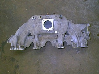
I already have the intake manifold modified currently running on the 4.0L motor I built last summer. Along with the Doug Thorley headers and 2.5" Borla exhaust. Here are some shots of the standard manifold, the new manifold with waaaay better runners and how they were modified.
I also have the 55mm throttle body bored to 62mm. That is also on the motor. In order to get the manifold to fit, I had to grind off the power steering boss on the manifold. I then made a bracket that bolts to the back of the power steering mount. This way I don't have to change any of the pulleys around, and still use the stock set up.
The new 2000 manifold has the A/C compressor on the opposite side of the motor. I didn't want to have to change everthing around. So I made a bracket to keep it as is.
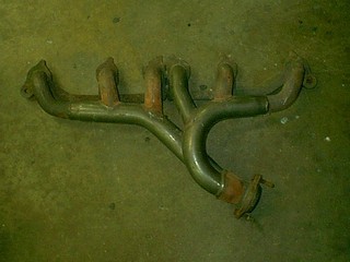
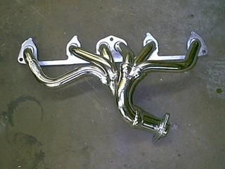
Here are some pictures of the old stock exhaust manifold, and the new Doug Thorley header.
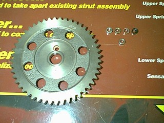
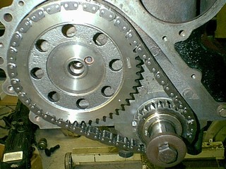
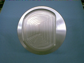
These are some shots of the timing gear that I modified to accept the SBC offset keyway to either advance/retard the cam timing from 0 degrees to 8 degrees.
I dropped off the head and block to be hot tanked and magnafluxed to make sure there are no cracks in them. I am waiting on the new valves so Sperry Engines can do the initial cut on the valve seats to open them up. Then I can start on the port work. Once the port work is done, they can go back to the shop to put the 3 angle valve job on them.
He can also measure up the block to make sure the 0.030" over pistons will clean up the cylinders.
The crank has to have 10mm milled off the end.�The crank cleaned up at 0.010/0.010".�
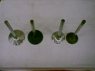
Here is a picture of the new 2.02" stainless intake valve compared to the old 1.94", and the 1.60" exhaust valve compared to the new 1.60".
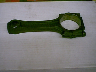
Here is the 4.2L rod before polishing the beam. Once they are all complete. I will balance them and install new ARP rod bolts. Then they will be sent off to be shot peened.
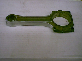
Here is the beam after being stressed relieved and polished
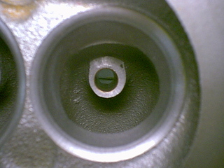
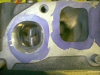
I went to the machine shop this morning as Scott had one cylinder done with the rough-in for the 2.02/1.60 valves, and bronze insterts installed in the guides. I wanted to get some before and after shots.
The finished installed height is going to be 1.630". The new springs I have ordered are Australian fine-wire performance springs that have 115# @ 1.625". Those should be about 110# @ 1.630". I am getting the valves, springs, retainers and keepers from http://www.engnbldr.com. Ted Stanford is AWESOME to work with.
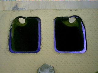
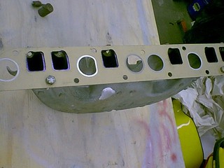
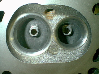
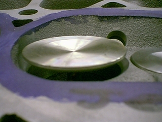
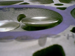
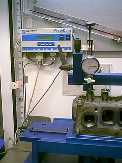
Here are the shots of the roughed in cylinder compared to the standard cylinder. I will be picking the head up on Friday after work to begin the port work. Once I get the port work complete in one cylinder, I will be heading over to the Super Flow Flow Bench to see where we are at with the numbers.
I also have to open up the combustion chamber from 57cc's to 62cc's. This will bring down the compression to 9.2:1, and allow me to run the stock 0.045" quench and unshroud the new, bigger valves.
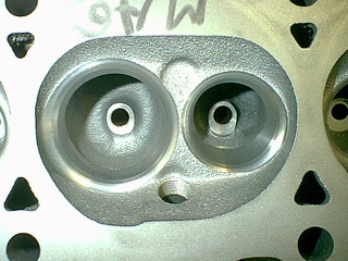
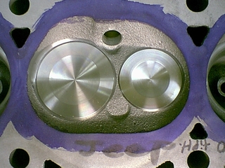
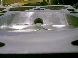
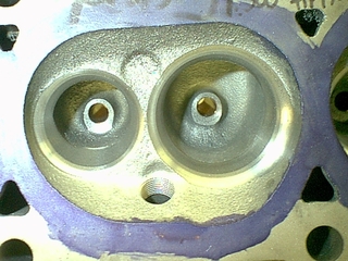
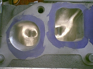
These are the shots of the head with the rough cut for the new larger valves:
They also put bronze knurled guides in.
I had them sink the valves a little deeper into the head for two reasons, to get a better valve spring installed height (so I don't have to buy custom valve springs) and to increase the chamber size.
The stock chamber size is 57cc's. I need to get up to around 64cc's, so I don't have to dish the pistons so large. I picked up 4cc's by sinking the valves. If I can get the chambers to around 64cc's, then I only have to dish the pistons an additional 8cc to around 19.2cc's total. This will allow me to run a 0.00" deck clearance, keep the stock quench of around 0.050" and keep the compression ratio at 9.0:1. I can still run 87 octane fuel.
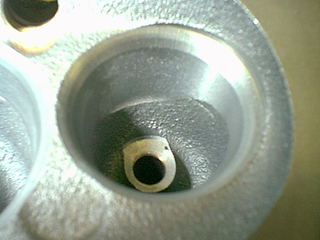
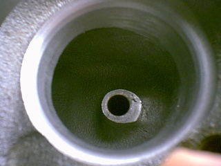
These are the before shots. I will be doing the port work this week on them. Once I get one cylinder done, I will take it over to the Super Flow Flow Bench and see where we are. I will post further on that as I get it done.
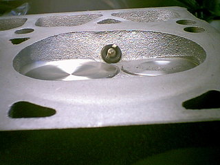
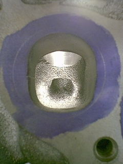
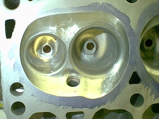
Here is the chamber before I start work. Also a picture of how deep the valves are set in the head:
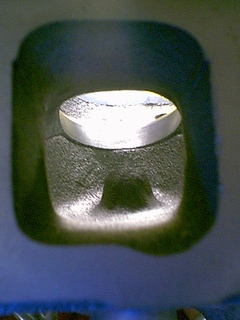
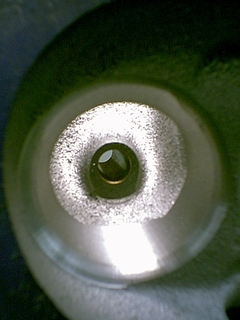
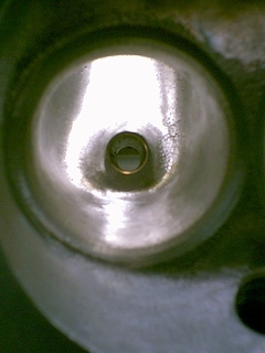
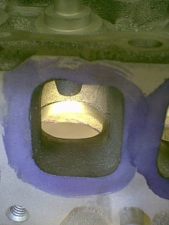
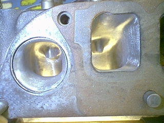
This is the exhaust port, a TON of work will be done on these before I am done:
This is the exhaust work. There will a lot of work done on the radius turn on this one:
I�am going to try something different with the head, though. I started with a 57cc chamber head. When the valves were done, I cc'd them and they are now at 61cc's. I am going to open up the chamber a tad to unshroud the valves.
I am only going to go into the front quench area about .050", but round out the area to match the head gasket. That is roughly equal to half the difference in size of the valves. The new valves are about 0.100" larger total.
I am going to keep the same swirl design in the back of the head, but also go into that area about .050".
On the sides, I am going to undercut the chamber a little to get a little more clearance. When I am done, the chamber size should be around 64-65cc's.
I can then run a Mopar head gasket at 0.045" compressed height, cut the block to run a 0.00" deck height, dish the pistons to 20cc's (which should be plenty to clear the valves) have a .045" quench height to keep the mixture in the chamber pure and avoid detonation.
If the head comes to 64 cc's that will yield a 9.15:1 CR, if they come out to 65cc's, that will yield a 9.06:1 CR. Either way, I am still good on pump gas.
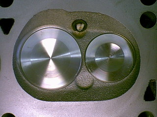
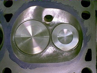
OK. I FINALLY took half a day off from golfing, and got to work on my new chamber design. The original chamber is 57cc's with 1.91"/1.50" valves. My new chamber has 2.02"/1.60" valves and the finished chamber is now 64cc's.
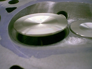
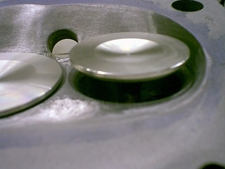
Here are the before shots. You can see how close the chamber sides are the valves almost 3/4 of the way around.
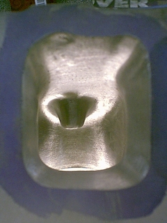
These are the after shots. You can now see that only abour a 1/5 away around is now shrouded by the chamber sides.
Tomorrow I will be working on the bowls, exit and entry ports and the small turn radius.
I took off an hour early from Toyota and did the following work. I went with Scott Minzenmeyer of Recreational Motorsports to check out a new coating place. They do similar work as Swain Tech, but they are locally. I have agreed to give them a try on my new motor. Swain Tech shipping is extremely high. I can drop my stuff off at this guys house. That WAAAAY more convient.
The company is called Cool Concepts (http://www.coolconceptspc.com) here in Amana, Ia. Mike is quite knowlegable, and doesn't BS. If he doesn't know the answer right off, he will get it. An EXCELLENT way to do business.
Here are the shots of the new exhaust port. I will be working on the intake tomorrow. It doesn't need quite as much work as the exhaust, but needs some finessing. Once I get it to where I want it. I will take it over to Sperry Engines and put it on the Super Flow bench and get some numbers. If they are satisfactory, I will take the measurements and make templates to match all the rest of the ports.
Here are the before shots:
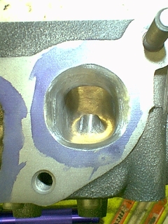
Here are the after shots:
This shot kind of gives you the size of the new port. It trumpets out at the end. As exhaust gas goes out it expands. If you can open that up sooner, it will move faster and draw air out, as well.
Once I get it on the flow bench. I will recheck the walls sonically. I kept track of how much I took off. When I started, the wall thickness back from the edges were about .250" thick. They got thicker as they got out towards the gasket surface. I just followed that contour.
Tonight I finished the intake side.
I didn't do a lot to the port other than blend the bowl, make the valve guide boss more aerodynamic and matched the gasket surface to the larger intake I made on the new intake manifold.
I didn't want to lose velocity, so I didn't go too much bigger.� I did some work on the short side of the roof.� Here are some before shots:
Here are the shots from after the work was done. You can see the work done on the short side of the radius.
Tomorrow, and over the weekend, I will put the final touches on the chamber and ports. Then I can sandblast the intake runner and bowl, and I have Thursday ready for the Flow Bench and Sperry Engines. I will post the numbers and any final tweaking that needs to be done.
Once I have the flow where I want, I will make my templates and take measurements so all cylinders are the same.
I am getting kind of stoked about the results. I am anxious to see where they fall, and to see how close I am to the results I want.
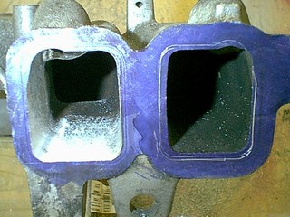
Here is a shot of both ports. They are much larger than the stock ports.
Here is a shot of the ports with the gasket matched to them. I trumpeted the exhaust port to get the gases expanding sooner into the pipe. This will help create a vacuum type effect as they expand, helping to draw out spent gases in addition to the piston pushing them out.
OK. The final calculations are in to figure the CR.
I used the following for block and pistons - assuming no dish to pistons for this equation. The dish will be calculated in another equation.
the volume of cylinder is Pi x (1/2 diameter) squared x length.
That equates to Pi x (1/2 bore) squared x stroke.
Breaking it down to simpler math (from Algebra) and using Pi = 3.14159265
bore x bore x stroke x 0.7854 = v
I am using a 0.030" overbore piston and a 4.2 crank with a stoke = 3.895"
3.905" x 3.905" x 3.895" x 0.7854 = 46.6489 C.I.
To convert CI to CC's, you need to multiply by 16.387084 = 764.5cc's.
Now you need to calculate the combustion chamber volume
This will also put my quench height at .045", or if I go with a 0.051" head gasket, that will bring my volume to 94cc' or drop my compression to 9.13:1.
We will have to see how much valve clearance there is.
The rods are all individually balanced, and the pistons are individually balanced to within .01" gram. They are packed and ready to be shipped out to Leigh to be dished from 11.2cc's to 18cc's.
The rods are currently out be shot-peened, and once the pistons are back from being dished I will check them for weight again.
I am hoping to get on the flow bench Thurs after work. We'll see, though. If I do I will take plenty of pictures.
The picture is kind of deceiving. They only flare out at the ends. They open up only in the last 13mm (about .500") to match the port, but they trumpet out in the last 13mm (for the guy who wants it in metrics. LOL)
I sonic checked the casting. I followed the contour of the casting underneath. It gets thicker towards the gasket surface. I followed that same contour.
It sonic checks to between 6-7mm (.250") all the way through. I, too, was worried about the wall thickness. I kept it to a minimum of that depth to avoid the water jacket issue.
I will running with the stock computer an adjustable MAP sensor and adjustable fuel pressure reg?
I finally took some time off to work on the motor again.
I got on the Super Flow flow bench for a night to see where I was at. I am glad that I took numbers before and after. My numbers aren't near what Dino's were in his article.
All the number were taken at 28" of H2O. The air temp was 80*. The bore adapter was 4.030" and there were no intake or exhaust adapters on the head at the time of testing.
The head is a 1994 - 7120 casting.
The stock numbers came out as follows, with 1.91/1.50 valves, no port work done:
I consider the port work and valve job to well worth the effort. There is potential for a whole lot of extra HP from this work.
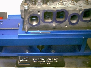
Here are some of the shots from the Super Flow bench, and Scott at Sperry Engines:
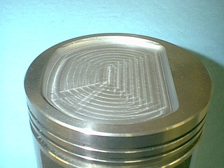
I also got the pistons back from being dished. All I can say is that I am NOT happy with the work and will be purchasing a new set of Sealed Power 677P pistons. One is going on my desk at work as a paper-weight. The rest will be put in a box in the storage shed.
I will just post the pictures, and let you see them. I is kind of hard to see what I am talking about. You can decide. I won't be using them. I won't bad mouth anyone on here, but I was VERY disappointed.
Anyway. I have a snowmobile motor to get ready for grass drags, so the next couple of weeks are shot. I will keep you all updated as thing develop.
Well. I am back at the Jeep motor.
I got a new set of pistons. I ordered the Sealed Power 677P. I tried to call SP and find out for sure if the dish was as listed in several other posts, and articles, as 17.5cc's. Even the techs could not tell me.
I got my new set. They sure didn't look like 17cc's. I went to the shop, greased the top, put the plate and CC'd the piston dish. 14cc's. A far cry from 17.5cc's. 17.5cc's would have yeilded a CR of 9.2:1. 14cc's is going to be too much compression for my liking in this motor. He we go again..they need to dished. Bend over, again.
I know I will NOT be contacting the previous person who dished my pistons, and made 6 paper weights for the people I work with. I gave them as gifts. At least THEY liked them. $90 for the set of pistons (ruined) $120 for machine work (that was juvenile AT BEST) and you have a $210 set of matching paper weights. The new set cost me $190. For what this guy cost me in parts, I could have just ordered a set from Hesco and be done with it. I need to give a big Shout-Out to the guy for blowing my budget out of the water. THANK YOU! not. (BTW - for the guy who did my piston dishes... There have been over 4,800 hits on this column in the 3 websites to which I am posting this. Thanks.)
Anyway. I also sonically checked the walls from the port work on the head. The thinest part of the wall was 0.258" thick. I did not want to run under 0.250 (especially on the exhaust side) as to not crack when cycling.
I will be making templates of the radii, openings and chamber. I will work on the chambers first. I will CC them all to within .5cc's, then go to the exhaust run, and then the intake run.
Once that is complete, I will send the heads over to have their 3-angle valve job done. That should help inprove the numbers a little, but I won't run it on the Flow Bench again.
I then need to mill the rocker arm bosses down and drill and tap them. Then the head work will be complete. All that will be needed is assembly. The FUN part.
I am going to polish the tops, and then have them thermal barrier coated.
I am already taking into account that I am only going to have 0.010" deck height, with a 0.043" head gasket. The chamber volume I have worked is already maxed out at 65cc's....the only place I have left to work with is the piston dish.
So I have 65cc chamber volume, 9.3cc's for the head gasket, 2cc's for the deck height and if I go 18cc's on the piston dish, that gives me a total volume at TDC of 94.3cc's.
The total volume of just the cylinder at BDC (for a 0.030" over piston) is 764.5cc's. 764.5 / 94.3 + 1 = 9.10:1
I found a guy that has a CNC machine, and he is going to dish them for me. I have worked with him in the past on custom one-off aluminum snowmobile stuff. I trust him, and he is VERY particular about his work. Unlike the pistons I got back from the previous machinist.
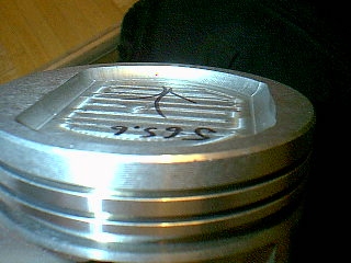
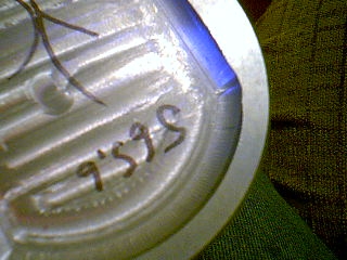
Here are the pistons as I got them back from the CNC guy (BTW - if anybody needs them dished, I can get them done for you. With professional results like these).
I requested 18cc dishes, and got 18cc dishes. I called Sealed Power and got the specs. 18cc's was the deepest I could go. They did not want the top of the piston to be less than 0.300" thick. They are exactly 0.300" thick, and the dish is exactly 18cc's. OUTSTANDING!
So this week will be polishing the tops so I can get them to Cool Concepts and have them put a thermal barrier coating on the top, and PC-9 on the side skirts.
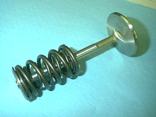
Here are the shots some of the new valve-train stuff, and some of the old stuff.
The old stuff - the Australian fine-wire valve springs. They have a finer wire than stock, but still have the same seat pressure. They allow larger lifts in a tighter area to prevent coil bind.
There is also a shot of the titanium retainers, and 10* keepers.
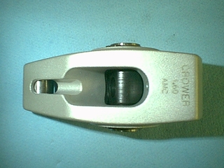
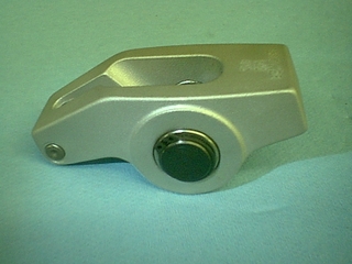
These are the Crower Roller Rockers. They run $269 for the set. They are aluminum rollers.